Tuesday, March 20, 2012

Day 6- Beta of a BJT

In this experiment, we will figure out the Beta(gain) of the npn bipolar junction transistor
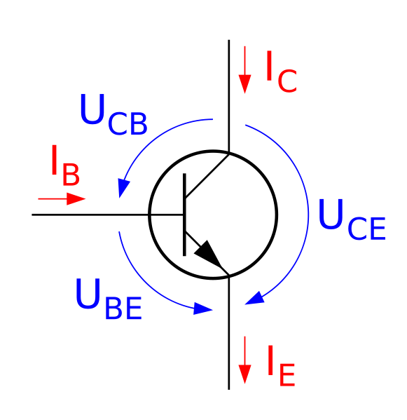
the basic schematic of the transistor is sown
With the relationship of
Ic=a*Ie
Ic=B*Ib
B=a/(1-a)

In this experiment, we set up the circuit as shown below

with a NPN type 2N3904 transistor


we will R1 (variable resistance box) and R2 of 100ohm(measured 98.2ohm) in the circuit

We will measure the change in R1 respect to the change in Ib and Ie

Measured V         Rb(Theoretical)         Rb(actual)            Ib                   Ie
6.05 V                       530 k ohm           529 k ohm          0.011 mA      1.36 mA
6.05 V                       265 k ohm           263 k ohm          0.021 mA      2.81 mA
6.05 V                       176 k ohm           176.6 k ohm       0.033 mA      4.18 mA
6.05 V                       132 k ohm           132.5 k ohm       0.046 mA      5.56 mA
6.05 V                       106 k ohm           106.4 k ohm       0.058 mA      6.98 mA

we can plot the graph with logger pro with Ie vs. Ib graph


Since we know that Ie=(1+beta)Ib
and we know the slope of the line is 116.2
116.2-1 will be the beta value of 115.2

According to the textbook, transistor has some saturated value that after the value, the transistor will acts like open and close switch. Since the kind of transistor we are using(BJT) is usually use as parts in amplifier, we do not want it function as switch. Instead, we want it to act like flow controller that control the desire current we want.  Thus, we are only interesting in the linear portion of the graph of the transistor.  


Day 5- Nodal Anylysis

In-order to construct a reliable power system for military usesage, the system must contain two power sources so when ever one of the source broke down the other back up source will still functioning the system.
Consider the schematic shown below


We can use nodal analysis to find the current went into and when out from the notes in-order to determine the suitable value for the voltage supplies

We can first establish the nodal equatinos in terms of the variable v1 and v2

(v1-v2)/100=v2/100 + (v2-v3)/220

(v2-v3)/220+ (v4-v3)/220=v3/1000
where v1 is 12V   v2 is 9v

we obtained V2=10.26V   V3=8.67V

Next, we can calculate the corresponding current leaving each battery
I_batt1= (12-10.26)/100=0.0174
I_batt2=(9-8.67)/220=0.0015


Then we can calculate the power supplied by each battery
P_batt1=0.2088W
P_batt2=0.0135W


Next, we devise the experiment to measure the battery current and the unknown node voltages


Data of the component


Component Nominal Value Measured Value Power Rating
R_C1 100+-5% 98 1/4W
R_C2 220+-5% 248 1/4W
R_C3 220+-5% 222 1/4W
R_L1 100+-5% 987 1/4W
R_L2 100+-5% 981 1/4W
V_bat1 12V 12.08 24W
V_bat2 9V 9.01 18W


Data obtained from the experiment


Variable Theoretical Value Measured Value Percent Error
I_bat1 0.0174A 17.12mA 1.60%
I_bat2 0.0015A 1.77mA 18%
V2 10.26V 10.34V 0.78%
V3 8.67V 8.33V 1.15%


We can see that our results are really close to our theoretical value within 5%. The only number that is off is I_bat2. The possible explanation should be lack in accuracy in our device. If we could get another multimeter that can read one more digits in the current, we will be able to decrease the percent Error significantly.


Next we can do some calculation to find the power delivered by the two batteries
P_bat = -0.2068W
P_bat2=0.01625W


Next, assume that we want V2=V3=9V, use the nodal equations derived in the previous part to find the required battery voltages

By solving the same equation, we are able to obtain that V1=10.98V
V2=9.9V

To do this experience, we need to replace the power supply with a variable power supply. The main difference of the power supply is that we are able to change the output voltage to any number within its limitation

From this
to these

This is one of the power supply that is provided in class. We used this power supply before for physics 4B, and the result is terrible due to the old technology it has. The output voltage is not constant but wondering around +-.5VFor another power supply, we found another one that is more modern and its more precise.

we obtain V2=8.92V  V3=8.8V  I_bat1=9.29mA I_bat2=8.03mA

Even thought the numbers are not close, but the percent errors in the voltage are all within the five percent. This experiment demonstrated the use of nodal analysis. 


Thursday, March 15, 2012

Day 4 - Freemat Calculation

The purpose of this experiment is to using computer programing(freemat) to do complicated matrix calculation without using hand to solve the question

We are given the circuit

And by solving the circuit using KVL and KCL
we are able to obtain the current at differnt branches

The result from setting up the equation and solving by matrices are shown below

The current through R3 is -0.186A


Tuesday, March 13, 2012

Day 3- Introduction to Biasing

There is time that we would like to connect two LED's to a device for an back up if one of the LED has failed. But the question is that the two LED's have the different ratings, one is 5V the other one is 2V
if we connect the LED in series, the LED with a lower voltage will burn out really fast and short the circuit. If we connect the LED in parallel, one of the LED will still have too much voltage across and then burn out
The goals of this experiment is to determine suitable power ratings for each resistor and then determine how long the 9V battery can power the circuit. Also, we are given further practice in measuring resistance, voltage, and current.

We have the schematic that illustrate the connection between the parts


 Where the current through the 5V LED is 22.75mA and the current through 2V LED is 20mA

First, we need to determine the equivalent resistance of each LED using Ohm's Law

R_LED1= 5/22.75mA=220Ω
R_LED2=2/20mA=100Ω

Next, we will need to determine the necessary values of resistors R1 and R2


I_R1 22.75mA
I_R2 20mA
V_R1 4V
V_R2 7V
R_1 175.8Ω
R_2 350Ω
P_R1 0.091W
P_R2 0.14W


Since we are limited by the certain discrete values in resistors, we need to determine the equivalent resistance by connecting multiple resistors in parallel, or series.


Possible Resistors Measured
R_1 (Ω) 2//150+100 172
R_2 (Ω) 150+2*100 347

Next, we will need to set up the circuits by using wires, alligator clips, electronic parts, and breadboard to demonstrate the circuit in class

After turning on the power, we obtain the picture


 Where the yellow LED "should" be rated at 5V and the green LED is rated at 2V

By measuring any currents and voltages across the LED we obtained the following data
Also, we were told to made some modification on our circuits
Configuration 1 : Both LEDs in the circuit
Configuration 2 : Remove LED2(remove R_LED2) from the circuit
Configuration 3: Remove LED1(remove R_LED1) from the circuit

*Configuration 2 and 3 illustrate when one of the LED failed but the circuit still work


Config I_LED1(mA) V_LED1(V) I_LED2(mA) V_LED2(V) I_supply(mA)
1 14.8 6.46 19.7 2.15 34.4
2 14.6 6.48 X X 14.6
3 X X 19.7 2.18 19.6


1. If the capacity of a 9V Alkaline battery is approximately .6A-hr, assuming the useful life of the 9V battery is just .2A-hr. With both LED's in the circuit on, how long can the circuit operate before the battery voltage goes too low

I_supply=0.0344A
T=A-hr*I = 5.8Hr

2. The % error b/w the achieved LED current and the desired value with both LEDs in the circuit? What was the cause of this error?
I_led1=35%
I_LED2=1.5%

The reason is the yellow LED is actually rated at 10V but not 5V, thus the current value will be off from the theoretical value

3. Determine the circuit efficiency when the both LEDs are in the circuit

Efficiency = 44%


4. If we operated the battery  to 6V, the circuit will not operate due to not sufficient voltage to drive both LEDs


Bonus: the reason why we must need both LEDs be in circuit without on of the LED will cause shortage on one of the branch, then cuz the current goes to high to burn out the LED


Sunday, March 4, 2012

Day 1 - Review Exericse : Using a multimeter

The first experiment we did is to understand how to use a multimeter properly by examining

 different methods to use it

Resistance Test
1. Set up the multimeter to read resistance, which is located at the Ω symbol

2. The multimeter will show " L " when the probes are not touching anything


3. When we touched the two probes together, the multimeter will have a reading of 0.001Ω due to the internal resistance of the wire

4. We grabbed four different resistors and recorded the theoretical and measured values


Resistors Colors
Value from Colors(Ω)
Measured Value(Ω)
Red, Orange, Brown
230
218
Orange, Orange,Red
3300
3290
Orange,Orange,Brown
330
329
Red,Black,Red
2000
2010

Few Tips on measuring electrical componets


  • Never measure resistance in a circuit when power is applied
  • Discharge capacitors before measuring resistance

Voltage Test

1. To measure the voltage across an element, we need to set the multimeter to read direct current(DC) mode.
2. Touch the probes at the two ends of a 9v battery, we should get a reading that is close to 9V
Since the school are not able to provide new 9V batteries to every group; instead, we use 9V power supply to measure the voltage.

 3. Last, we tested the wall wart(adapter)plugs,
the value we get is 23.0V

Testing transformer-based adapter

when we measure a adapter that has labeled 18V, the value we get is 23V. The reason is that the adapter is really old one plus its an unregulated. That means, the voltage output is not constant.

When we use two clips to attach a 150 ohm resistor across the probes, the voltage reading did not change

Next, we set up the circuits as shown in the picture, with one 150 ohm resistor, 1 LED, and a power supply.

We measured the voltage at different places such as when we measure the voltage drop across the 150 ohm resistor, we got a value of 2.41V

When we measured the voltage drop across the LED  we got 2.13V

When we measured the voltage drop across the power supply, we got 4.54V

Out data makes sense if we added 2.41+2.13+4.54V  , we will get value close to 9.08V, which is the initial value of the voltage supply. Few reason that caused the inconsistency in values such as wired also dissipated some energy .

Current Test

We used the same set up as we used in the voltage testing experiment. This time, we were told to measure the current. To measure the current, we need to set the multimeter to A, which means ampere.  Then we need to break the circuit and insert the probes from the multimeter into series with the circuits to connect the circuit. If we do not measured in series, we might able to burn the fuses inside the multimeter.
The current value we measured is 15.9mA

Day 2- Introduction to DC circuits

When doing theoretical questions on paper, we always assume that wires in the circuits are perfectly conductive, without any resistance. In reality, wire has resistance proportional to the ratio of its length and cross section area.

For example, if we have to operated a device that is connected with a wire which is thousands of feet in length, the resistance in the wire will add up into a significant number that will effect the circuits if we did not put it into consideration.

In this experiment, we will consider a circuits such as this

We will consider few assumptions
1. Load is rated to consume 0.144W
2. Minimum voltage across the load is 11V
3. The battery has a capacity of 0.8Ahr and will remain constant at 12V

The goal of this experiment is to determine
1. The maximum permissible cable resistance while the circuit still work functionally
2. The maximum distance the battery and load can be separated if we use AWG#30 cable
3. Distribution efficiency
4.Approximate time before the battery is out of power

Since we know the power rating on the load, we are able to determine the load resistance

P=V^2/R
and by rearranging the equation and solve for R
we will get a R value of R_load=1000Ω


Next, we will set up the experiment as shown in the schematic
 We will first set up the power supply to 12V, and by increasing the cable resistance until the voltage drop to 11V, that will be the maximum resistance of the wire


The yellow resistance box will represent the resistance of the cable and the part located in the bottom left corner of the picture will be the 1000Ω, which is the load


We will measure the voltage and the current at different location as shown below


Next, we will measure any componets before assembling the circuit and note the ratings


Parts Nomial Value Measured Value Tolerance Rating
power supply 12V 12.14
2A
R_load 1000 978 5% 0.25W


Next, we connect the circuit and measure the voltage across the battery, current, and the voltage acrosst he load.

we got

Measurement
V_Load 10.97V
I_batt 11.1mA
R_cable 101Ω

 After the measurement,  we disconnect the wiring place all the part to its original location


Few question that we are able to solve after do some calculation


a. The time to discharge the battery is given by the formula Amp-hr=amps*time
where we know he Amp-hr, and the amps, we can calculate the time, which is 72.07 hrs


b. To calculate the distribution efficiency, we need to find the power of the load, the cable, and the power that is supplied by the power supply
To find the efficiency is P-out/(P_out+P_lost)


P_out 0.1205W
P_in 0.0125W
efficiency 90.60%

C Are we exceeding the power capability of the resistor box, which is 0.3W
NO, becuase P=I^R=0.0124W

D Given that the resistance of AWG#30 wire is 0.3451Ω/m, determine the maximum distance b/w the battery and the load
Since we know the resistance of the cable and the linear resistance density, we can calculate the lenght will be 3.19m